
Additional Images
Rear Panel Description
EAS1 Programming Form
Click here for product documentation/instructions and setup software
Been let down by EAS equipment no longer supported by other manufacturers? Contact us to request a quote on compliant, fully-supported EAS equipment compatible with our CAP-DEC1 Common Alerting Protocol equipment. We also offer high quality, versatile AM/FM/WX radio tuners for receiving messages from your Over-the-Air (OTA) monitoring assignments.
Model EAS-1 is now available with an optional telephone interface for inserting an emergency message from a remote location with a DTMF telephone keypad. The EAS-1 requires 3.5″ of rack space.
The EAS-1 with CG has a character generator built into a cabinet that requires 5.25″of rack space. This unit with a dedicated character generator will put a crawl on the television screen for a cable system or TV station.

Units with firmware v9.8+ meet 6th Report & Order requirements including accepting the “six-zero” (000000) location code as the national location code and including the NPT (national periodic test) event code as a required event code by default.
- Alert messages can be originated from a remote location with a telephone DTMF keypad.
- 5 bi-directional RS232 inputs/outputs for computer modem, remote sign board, character generator and auxiliary panel.
- 6 Audio inputs on standard models. All audio inputs and outputs are transformer isolated from encoder-decoder board.
- Manual or automatic mode keypad selectable.
- Automatic interruption of stereo program lines when pre-selected header code is received while in automatic operation for insertion of alert message on transmitter.
- 2 minutes of digital audio storage (5 khz).
- 5 programmable relays to supply contact closures to handshake with automation equipment or signal other equipment.
- 25 pin parallel printer port for external printer to keep E.A.S. log.
- An auxiliary balanced 600 ohm output through a co-axial BNC fitting to either go directly into the FM exciter or modulate a second transmitter.
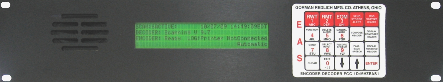
- Alert is displayed on a 4 line 40 character backlighted LCD display for rapid interpretation of alert message. Alert message can also be scrolled on a remote sign board, a computer screen or with a character generator on a video monitor.
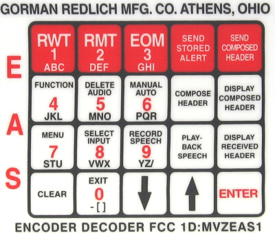
- 20 key keypad to construct alert messages header code, set modulation levels or set input levels. Header codes can be edited or dumped on practice runs.
- Can have 1 or 2 password codes. One for composing a header code and another that will be known only by those who will be adjusting the equipment.
- The complete required weekly test, the end of message code, sending a stored alert or sending a composed header can be done from either the keypad on the encoder-decoder or with a remote push button in the “on-air room”. If you choose to just forward the header code and the E.O.M., the audio portion of the message can be deleted from either the keypad or a remote push button in the “on-air-room”.
- Automatic reset of decoder after 2 minutes.
- The stored audio message can be routed to the speaker for review so that the urgency of the message can be gauged. The message can then either be cancelled or sent on.
- Will operate over audio input levels from 0.14 V to 2 V R.M.S.
- Diagnostic information can be printed out on a printer if unit is malfunctioning and can be faxed to us for analysis.
- Quality 2 1/2 inch 8 ohm front panel QUAM speakers for clear audio.
- Non-volatile memory and non-volatile voice storage.
- 4 layer board with all signal traces on top and bottom and all IC’s mounted in sockets for ease of repair.
- Compatible with both RS232 and FSK modes of the CAP-DEC 1 CAP-to-EAS decoder.
- Unit has a CMOS EPROM 32 PIN 1MB (128 K x 8) for future changes.
- Easily configurable using the Gorman-Redlich Setup Software (Windows XP/Vista/7 and DOS compatible)
Additional Product Images
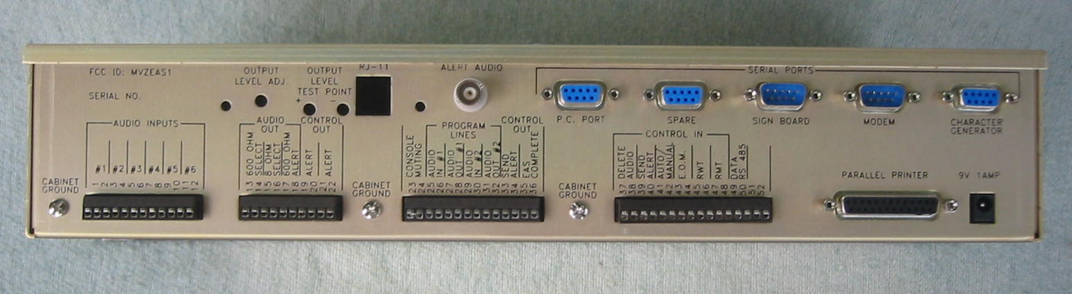

Rear Terminal Description
| Terminal Label | Description |
| 1-12 Audio In-Monitor inputs 1-6 | Six pairs of audio inputs are each coupled to the decoder by 600 ohm to 600 ohm isolation transformers. These six audio sources are scanned for EAS alert messages. |
| 13-14 Audio Out – 600 ohm select | Balanced 600 ohm continuous audio output from an operator selected monitor input. Any channel #1 – #6. |
| 15-16 Audio Out – 8 ohm select | Balanced 8 ohm continuous audio output from an operator selected monitor input. Any channel #1 – #6. |
| 17-18 Audio Out – 600 ohm alert | Balanced 600 ohm audio output from the channel carrying the alert message. This output is gated on when the alert takes place. |
| 19-22 Control Out – Alert | Two contact closure outputs can be used to signal remote control equipment, automation equipment, or to activate a remote bell or lamp. |
| 23-24 Console Muting | These terminals allow console muting of the panel speaker when the unit is installed in an on/air room. |
| 25-32 Audio In/Out Program Lines A/B | Eight terminals for balanced 600 ohm stereo program audio lines. Via these inputs and outputs, the encoder interrupts the program audio to insert the alert message. |
| 33-34 Control Out – Send Alert | Contact closure which can complete the circuit for an external relay coil for a coaxial relay during the time the encoder is sending an alert signal. This will allow a low impedance coaxial alert feed directly into a transmitter exciter circuit, thus bypassing all audio processing or energizing external relays to put the alert on additional transmitters. |
| 35-36 Control Out – EAS – Complete | Contact closure output to signal automation equipment that the EAS interruption is completed. |
| 37-38 Control In – Delete Audio | Contact closure input for deleting the 853/960 attention signal and the audio message portion of a received alert message. The encoder will send only the FSK (frequency shift keying) header and EOM (end of message) portions. The contact closure would be supplied by remote switch or remote control equipment contacts. |
| 39-40 Control In – Send Alert | Contact closure input to tell encoder to send a stored alert message now. |
| 41-42 Control In – Local | Contact closure input to switch the encoder from automatic to manual control. |
| 43-44 Control In – EOM | Contact closure input to remotely send EOM (end of message). FSK code. |
| 45-46 Control In – RWT | Contact closure input to remotely send RWT (required weekly test). FSK header code and FSK EOM code. |
| 47-48 Control In – RMT | Contact closure input to remotely send RMT (required monthly test). FSK header code and dual tones. |
| 49-50 Data In/Out – RS485 | Serial data option for future remote control equipment. |
| 51-52 | Not currently used. |